Working Distance For Smd Soldering Microscope Uk
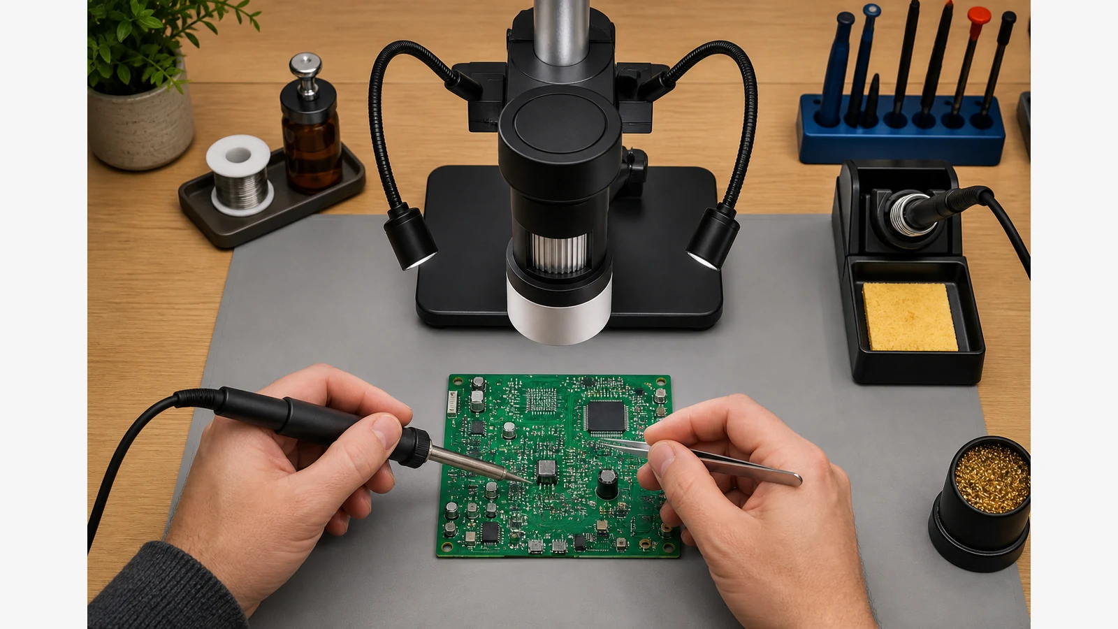
For active SMD soldering on a UK bench, prioritise under-lens clearance for your iron, tweezers and hot air—not the highest advertised magnification. If the tip cannot reach the pad while the board is still in focus, the zoom figure on the box is irrelevant.
Why short working distance fails on real boards
Many compact USB pens and low pillar stands focus the board only when the lens sits close to the surface. Once you try to add a soldering iron or hot-air nozzle, there is nowhere to put the tool. Guidance for choosing a solder microscope repeatedly stresses that the lens-to-object distance must leave room for hands and tools, not just a clear still image.
Forum technicians discussing SMD rework often treat roughly 100 mm or more of clearance as a practical floor when hands and soldering tools must work under magnification. UK marketplace soldering kits also market around that distance as a comfort feature for motherboard work—useful as a shopping cue, not as a universal rule for every tip shape or board thickness.
Bench checklist before you buy or raise the stand
- Measure with your real tools. Focus a scrap board, then try your usual iron tip, tweezers and (if you use it) hot-air nozzle under the lens. Note whether the tip can approach at a natural angle without fouling the housing.
- Check the stand type. A low fixed pillar may force you into high zoom with almost no clearance. A taller pillar, boom arm or riser strategy matters more than chasing another “X” number.
- Confirm usable zoom at that height. Raise the lens until tools fit, then check that pads and joints are still readable at a working magnification—not a cropped, blurry digital zoom.
- Plan lighting after clearance. Only once tools fit should you tune side lighting; glare fixes will not help if the iron never reaches the joint. See our related note on reducing microscope glare on PCBs.
Who should not over-spend on clearance
If you only photograph or inspect boards and never put tools under the lens, paying for maximum working distance may be unnecessary. Inspection-only workflows can often use shorter stands if documentation is the main job—compare that path when you weigh digital versus stereo for electronics repair.
Next decision if clearance still fails
Change stand height or stand type before chasing higher zoom claims. Pair clearance with a workflow that matches how you actually solder—standalone screen versus PC-tethered USB is a separate choice covered in LCD versus USB microscope setups. For PCB soldering context on this site, you can also read the existing digital microscope PCB soldering guide.