How To Reduce Microscope Glare On Pcb Uk
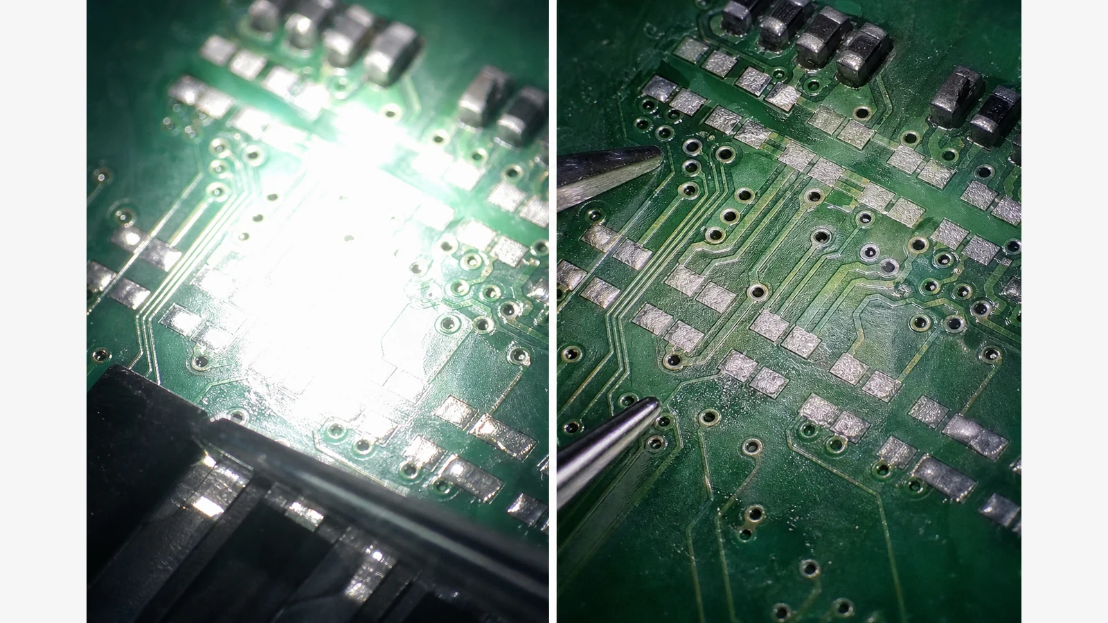
To fix washed-out solder joints under a microscope, move from a bright overhead ring wash to angled, dimmable side lighting and lower intensity before you buy a new camera. Shiny flux and copper often hide pad edges even when magnification looks “high enough”.
Why brighter light often makes pads worse
Technicians report that dense ring lights can wash green soldermask and chip markings with specular glare. Changing the incidence angle—using gooseneck or side LEDs instead of a direct wash—is a common remedy discussed in micro-soldering lighting evaluations. Lighting quality itself is a core selection factor for solder microscopes when ambient light is insufficient, so treat lamps as part of the tool, not an afterthought.
A UK bench lighting sequence
- Dim first. Drop intensity until copper and pad outlines regain contrast. Brightness is not the same as clarity.
- Angle side lights obliquely. Aim goosenecks or bar lights so the reflection misses the camera path; avoid a hot ring centred on the board.
- Block remaining specular hotspots. Use a small card, matte shield or lamp repositioning so one shiny joint does not blow out the whole frame.
- Reassess zoom only after contrast returns. If lettering and pad edges are readable, stop escalating; polarised accessories may be optional rather than mandatory.
Ring light versus gooseneck
Ring lights are convenient and even, but on glossy flux they often create the wash that hides markings. Gooseneck or dual side LEDs take longer to aim and usually restore pad contrast faster. Pair this sequence with enough under-lens clearance so lamps and irons can coexist—see working distance for SMD soldering.
When not to escalate
If chip lettering and joint outlines are readable after angle and intensity changes, you may not need polarisers, new cameras or higher zoom. Escalate only when contrast still fails after dimming and oblique lighting. For tool-type choices after lighting is sorted, compare digital versus stereo for electronics and magnifier lamp versus digital microscope.
Related reading on this site: digital microscope for PCB soldering.